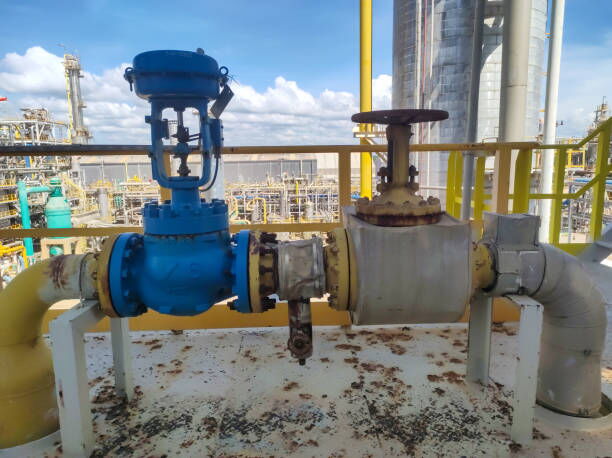
Control valves are essential components in industrial processes, regulating the flow of fluids to maintain desired conditions such as pressure, temperature, and liquid levels. Understanding the various failure modes of control valves and implementing appropriate fail-safe measures are crucial for ensuring safe and reliable operations.
In industrial settings, control valves are equipped with fail-safe positions to address emergency situations. The primary fail-safe positions include:
1. Valve Fully Closed: In this position, the valve shuts off the flow completely, preventing any fluid passage. This is typically used when it is essential to stop the flow to avoid hazards.
2. Valve Fully Open: Here, the valve allows maximum flow, which can be necessary to prevent pressure build-up or to ensure continuous cooling in certain systems.
3. Valve in the Last Position: The valve remains in its position at the time of failure, maintaining the last set flow condition. This is useful when the last position is considered safe under failure conditions.
4. Valve Continues to Control: The valve continues to operate based on the last received control signal, maintaining process stability until corrective actions are taken.

To bolster the reliability of control valves during emergencies, additional backup systems can be integrated:
A capacity tank stores a limited supply of instrument air to maintain the regular operation of the control valve for a limited period, typically around one hour or more. The design of the tank's volume and capacity should align with the customer's requirements to ensure adequate support during air supply interruptions.
A high-pressure cylinder with a backup gas, usually nitrogen (GN₂), is kept on standby. If the instrument air supply pressure drops below 50 psig, the backup gas takes over, supplying the pneumatic control system. The high pressure of the backup gas allows for several hours of continuous operation, providing sufficient time to address and recover from an emergency loss of instrument air supply.
In the event of instrument air supply pressure loss or power loss, the actuator's spring mechanism plays a pivotal role in driving the control valve to its designated fail-safe position. The bench-set spring range of the pneumatic actuator determines whether the valve will move to a fully open or fully closed position upon failure. This mechanism ensures that the valve defaults to a safe state, mitigating potential risks associated with uncontrolled fluid flow.
Pneumatic globe control valves, commonly used for their precise throttling capabilities, can experience several typical failure modes:
The diaphragm actuates the valve stem. A rupture can lead to loss of control, causing the valve to fail in its default position.
Over time, the actuator spring may weaken or break, compromising the valve's ability to return to its fail-safe position during an emergency.
Corrosion, debris, or inadequate lubrication can cause the valve stem to stick, preventing proper valve operation and response to control signals.
The positioner ensures the valve reaches the desired position. Malfunctions can result in incorrect valve positioning, leading to process instability or safety hazards.
Contaminants in the instrument air supply, such as moisture or oil, can impair actuator performance, leading to sluggish or erratic valve movements.
To minimize the risk of control valve failures and enhance system reliability, several strategies can be implemented:
Implementing a routine maintenance schedule helps identify and address potential issues such as wear, corrosion, or contamination before they lead to failure.
PST is a technique used to test a percentage of the possible failure modes of a shutdown valve without the need to fully close it. This method assists in verifying that the safety function will operate on demand and is particularly useful for high-integrity emergency shutdown valves (ESDVs) where full closure during testing is impractical.
Conducting FMEA involves systematically evaluating potential failure modes within a system and their effects on overall operation. This proactive approach aids in identifying critical components and implementing corrective actions to prevent failures.
Incorporating redundant components or diverse technologies can provide alternative pathways for control, ensuring that a single failure does not compromise the entire system.
Utilizing smart positioners and sensors enables continuous monitoring of valve performance, allowing for early detection of anomalies and facilitating predictive maintenance strategies.
A recent incident in Midland, Texas, underscores the critical importance of reliable control valves in municipal water systems. The city faced water pressure issues due to a combination of a failed pressure valve and the proliferation of invasive zebra mussels at the water treatment plant. The valve failure, compounded by the unavailability of immediate replacements, led to significant disruptions in water supply. This situation highlights the necessity for proactive maintenance, availability of spare parts, and the implementation of advanced monitoring systems to prevent similar occurrences in the future.
Understanding and addressing control valve failure modes are vital for maintaining the safety and efficiency of industrial processes. By implementing fail-safe positions, integrating backup systems, conducting regular maintenance, and employing advanced diagnostic tools, industries can mitigate risks associated with valve failures. Proactive strategies not only enhance operational reliability but also safeguard personnel, equipment, and the environment from potential hazards.