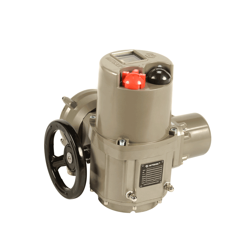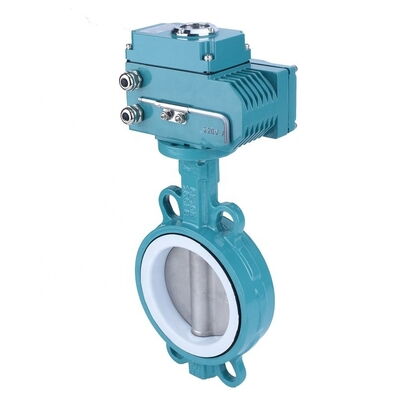
In the world of industrial automation, quarter-turn electric actuated valves play a pivotal role in controlling fluid flow across various sectors, including oil and gas, water treatment, chemical processing, and power generation. These valves, which include butterfly valves and ball valves, are designed to rotate 90 degrees (a quarter turn) to open or close, providing efficient and reliable flow control.
Electric actuators convert electrical energy into mechanical torque, enabling precise valve operation without manual intervention. These systems are widely preferred due to their remote operation capabilities, high precision, and integration with modern control systems. This guide explores the working principles, installation procedures, troubleshooting techniques, and maintenance best practices for quarter-turn electric actuated valves.
Electric actuators consist of several critical components that work together to ensure smooth valve operation:
Electric Motor – The primary power source, available in AC (Alternating Current) or DC (Direct Current) configurations.
Gearbox – Reduces motor speed while increasing torque to rotate the valve.
Limit Switches – Define the open and closed positions, preventing over-rotation.
Manual Override – Allows manual operation during power failures or maintenance.
Control Circuitry – Processes input signals (e.g., 4-20mA, 0-10V, or digital commands) for automated control.
Housing & Enclosure – Protects internal components from dust, moisture, and harsh environments (rated IP65/IP67/IP69K).
A key factor in actuator selection is torque—the rotational force needed to open or close the valve. The actuator must provide at least 30% more torque than the valve’s breakaway torque (the initial force required to start movement).
Breakaway Torque – Highest torque needed to initiate valve rotation.
Running Torque – Sustained torque required to keep the valve moving.
Seating Torque – Additional force needed to ensure a tight seal (critical for bubble-tight shutoff in ball valves).
If the actuator’s torque is insufficient, the valve may fail to open or close completely, leading to leaks or system inefficiencies.

Before mounting the actuator, perform the following checks:
Verify Compatibility – Ensure the actuator’s torque, voltage, and control signals match the valve’s specifications.
Inspect for Damage – Check for shipping damage, dents, or misaligned components.
Confirm Mounting Standard – Most actuators follow ISO 5211 flange standards for seamless integration.
Align Valve & Actuator Positions – Both should be in the same position (fully open or closed).
Secure with High-Tensile Bolts – Use locking washers to prevent loosening due to vibration.
Ensure Proper Sealing – Apply thread sealant to prevent leaks in pressurized systems.
Power Supply Wiring – Connect to the correct voltage (e.g., 24V DC, 120V AC, 240V AC).
Control Signal Wiring – Follow the manufacturer’s diagram for open/close commands and feedback signals.
Grounding – Essential to prevent electrical hazards and signal interference.
Set Open Position – Manually rotate the actuator to the fully open position and adjust the limit switch.
Set Closed Position – Repeat for the closed position to ensure full 90° rotation.
Functional Test – Run the actuator to confirm smooth operation.
Manual Override Test – Ensure the handwheel or lever works in emergencies.
Leak Test – Pressurize the system and check for leaks.
Despite their reliability, electric actuated valves can encounter operational problems. Below is a detailed troubleshooting guide:
Possible Causes:
Power Supply Failure – No voltage or incorrect voltage.
Thermal Overload – Motor overheats and shuts down.
Blown Fuse or Tripped Breaker – Electrical protection triggered.
Solutions:
Check power supply with a multimeter.
Allow the motor to cool if overheated.
Replace blown fuses or reset breakers.
Possible Causes:
Insufficient Torque – Actuator cannot overcome valve resistance.
Mechanical Obstruction – Debris or misalignment blocks movement.
Limit Switch Misalignment – Incorrectly set travel limits.
Solutions:
Verify actuator torque matches valve requirements.
Inspect valve stem and seat for blockages.
Recalibrate limit switches.
Possible Causes:
Loose Wiring Connections – Poor electrical contact.
Signal Interference – EMI from nearby power cables.
Faulty Control Board – Damaged electronics.
Solutions:
Secure all wiring connections.
Use shielded cables for signal wires.
Replace defective control modules.
Possible Causes:
Improper Engagement – Override mechanism not fully disengaged.
Gear Damage – Stripped gears due to excessive force.
Solutions:
Follow manufacturer’s override instructions.
Inspect gears for wear and replace if necessary.
To maximize valve lifespan and performance, implement a preventive maintenance schedule:
Inspect for leaks, corrosion, or loose bolts.
Verify electrical connections are secure.
Lubricate gears and moving parts.
Test manual override functionality.
Replace worn seals and gaskets.
Perform full calibration and torque testing.
Quarter-turn electric actuated valves are essential for modern industrial automation, offering precision, reliability, and remote control capabilities. By following proper installation, troubleshooting, and maintenance procedures, engineers can ensure optimal performance and longevity of these critical components.
For industries requiring fail-safe operation, high torque, or hazardous environment compliance, selecting the right actuator is crucial. With advancements in smart actuators (IoT-enabled diagnostics, predictive maintenance), the future of valve automation looks even more efficient and interconnected.
By adhering to this guide, professionals can minimize downtime, reduce maintenance costs, and enhance system reliability—ensuring smooth operations in any fluid control application.